• Home
  • Resume
  • Experiences
  • Blog
  • Story about myself
  • Contact

Charlie's chat room

EAE6320 Assignment13

11/27/2015

0 Comments

 
Picture
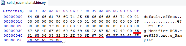
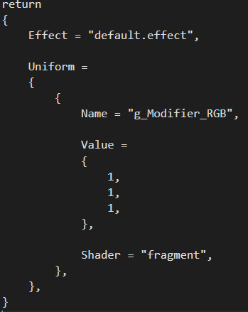
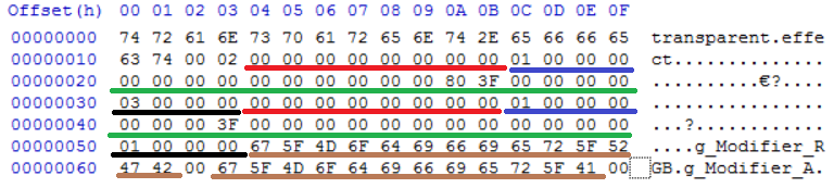
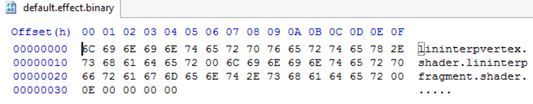
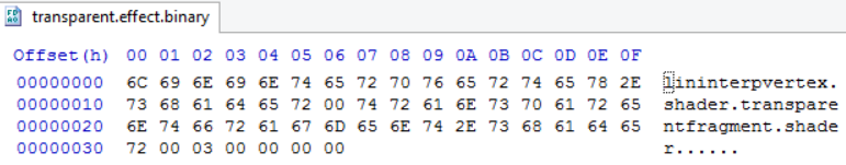
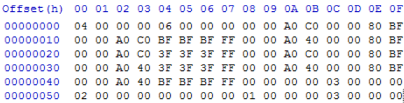
above is the material binary file with solid eae6320 texture. After array of uniform data, comes array of texture data, which contains pairs of texture path (in red) and sampler uniform name (in blue). These will be extracted to make temp string vectors in load time.

I choose to create another texture2d class just to be more structured. At graphics initialization, a pointer to d3d device is copied in initialize() method where gl implementation leaves it blank. At load time, texture data and sampler handle will be set in material ctor. At run time, texture is applied in setting material uniform function in material class by calling Texture2D::SetMaterial(size_t unit) where unit is unused by d3d implementation. Material class stores vector of textures of current material.

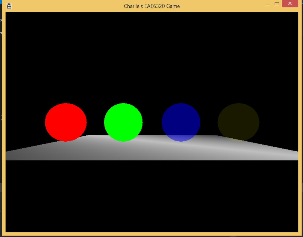
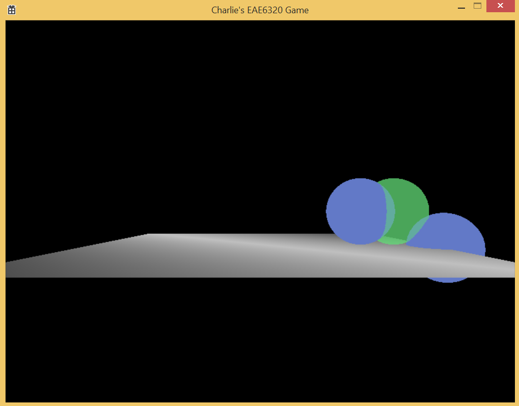
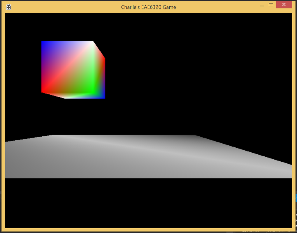
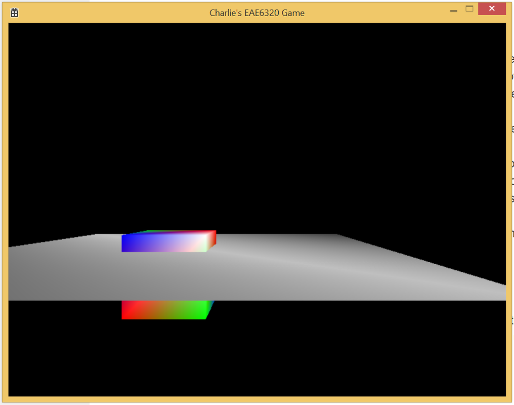
The following two figures are separately my d3d and gl screenshot:
Picture
Picture
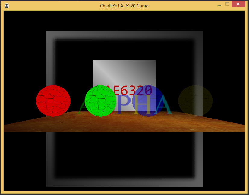
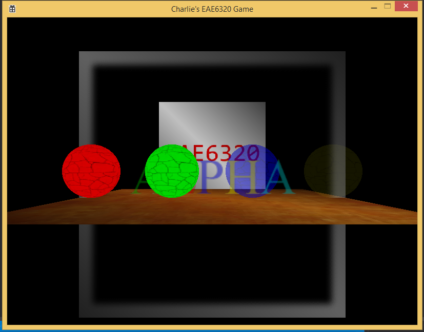
As JP informed, gl implementation looks more "blurry" than d3d version. I'll add scaling in my next assignment also.

Here's my executable
assignment13.zip
File Size: 2594 kb
File Type: zip
Download File

0 Comments

EAE6320 Assignment12

11/25/2015

0 Comments

 
The straight benefit for using materials is that a lot of objects share the same effect while having different appearance. Take iron table and wood table as example, they share the same rendering setting such as same shader, depth test settings, while they use different color or texture during rendering to show themselves as iron or wood. So we can still keep the old way that effect may not need to be changed while rendering several objects.

Here's a screenshot of my human-readable material file:
Picture
Effect path is extracted for reading effect binary at run time. Then there's a Uniform block which contains arrays of uniforms. In each block, uniform name is used to set handle at run time. Then there comes the value block which contains 1 to 4 floats to meet different vector size need in shader. Then shader type is specified for Direct3D to specify which shader should we get const table and then get handle from. 

The following is a screenshot for my direct3d transparent blue material:
Picture
As mentioned above, effect path comes first. Then comes the count of uniforms, which is optional. Then comes array of uniforms. The red line part is the uniform handle, which is a 64 bit nullptr as default. Then the blue part shows the shader type, in my case vertex is 0 while fragment is 1. The number of values we need for a uniform is flexible but i choose to hold it in a fixed size container (4 floats). The count is needed to know how many values is actually useful in run time. The green part contains 4 float values. Then comes the count of values shown in black part. There's no particular reason for choosing this sequence. Then after the array of uniforms, there comes the name array for uniforms shown in brown. This is used to set handle at load time.

Different platform has different binary material because type for handle is different and they have different default values. It's the same between configurations in my case though.

Here's a screenshot of my scene:
Picture
Same mesh is used for all four spheres. The mesh vertex color is white. The red sphere has is solid material with rgb (1, 0, 0) so only red passes the filtering. Green is similar just with rgb (0, 1, 0). These two materials use default.effect which disables alpha blending. As for blue and yellow shperes, they have separate rgb of (0, 0, 1) and (1, 1, 0). Blue material has an opacity of 0.5 while yellow has it as 0.1. In their shared effect, alpha blending is enabled and also exists fragment shader uniform for setting alpha independently.

Here's my executable:
assignment12.zip
File Size: 57 kb
File Type: zip
Download File

0 Comments

EAE6320 Assignment11

11/17/2015

1 Comment

 
The exporter project doesn't have any dependency relation with any other projects in the solution. The output from the exporter is used by manual process to export lua mesh file. The builder projects then use the mesh file to generate the binary. So no projects should be dependent on exporter project. Exporter project doesn't depend on any projects to build the mll.

Here's a screenshot of plug-in manager:
Picture
Here's a screenshot of exporter debug:
Picture
Here's a screenshot of my scene:
Picture
Here's a screenshot of human-readable effect file:
Picture
There's no particular reason for choosing this format. The structure is rather plane because contents are pretty much unique entries. For the optional render state, default value will be set if absent from lua file as JP suggests.
Also using an uint32_t as optional bits container. I'm currently using bit 0 for alpha transparency, bit 1 for depth testing, bit 2 for depth writing and bit 3 for face culling. To set a bit, use container |= 1 << BIT_INDEX. To get a bit, use container & 1 << BIT_INDEX.
​
Here's screenshot for default effect and transparent effect binary:
Picture
Picture
The structure of binary effect is first file name for vertex shader followed by \0, then name for fragment shader followed by \0, then a 4 byte unsigned int followed by \0 (which is not necessary). For default effect, the unsigned int value is 0x0000000E indicates 1110 on lowest 4 bits. This means we're disabling alpha transparency, enabling depth testing, writing to depth buffer and also face culling. For transparent effect, the value is 0x00000003 which means 0011 on lowest 4 bits, indicating we're enabling alpha transparency and depth testing while disabling writing depth buffer and face culling. The optional bits are added to the last part of the binary file just by intuition. When reading binary file, this value is get by calculating the offset by strlen(vertex) + strlen(fragment) + 2, then cast the pointer into a pointer to uint32_t.

For alpha blending, we're currently using srcColor * srcAlpha + backColor * (1 - srcAlpha), which is intuitive. A blue glass with transparency of 0.5 will appear 0.5 of its own color and another 0.5 of what's behind the glass in observers' eyes. The reason to render from back to front is because transparent objects doesn't write to depth buffer, so if there're solid objects rendered behind transparent objects both in render sequence and z value may write to z buffer and cover the transparent objects, making that visually unrealistic. We need to render objects that doesn't write to depth buffer last so that we can get blended color from the basic calculation above. Face culling should also be disabled for transparent objects because when object is transparent we can clearly see its back side.

Here's my executable:
assignment11.zip
File Size: 59 kb
File Type: zip
Download File

1 Comment

EAE6320 Assignment10

11/8/2015

2 Comments

 
Picture
We have three transformation matrix in vertex shader. The first one transform 3d vertex from local coordinate to world coordinate. Speaking of box, we consider the local coordinate center as the center of the box. A vertex at (1, 1, 1) in its local coordinate will be first transformed to work space using local_to_world transformation matrix. World space is self-explained that that's where every object stays in. Things with same local position could have different position in world, and vice versa. Then we need to perceive the world from camera, this means we need to apply a world_to_view transform to the previous result. The default position and direction of camera is at (0, 0, 1) and looks at (0, 0, -1) direction. We apply that second transformation to get where things are from the whole view plain. Still, we need another transformation matrix to apply camera specific parameter where open angle and truncation planes come into place. After applying these three matrix, we get the picture above.
Picture
Here's a picture where two objects intersect. Our depth buffer is 16 bits which means 65536 differences. From our far plain to near plain we have 100 - 0.1 = 99.9 unit length. 99.9 / 65536 = 0.0015 is the minimum difference we can tell in depth buffer. In each frame, the depth is cleaned to be the value representing the furthest distance. OpenGl use a float between 0 to 1 here. 1 means the furthest. Then we start to draw the first object. When drawing a pixel for the first object, the first object that could be seen is definitely nearer to the screen than the furthest truncation plain. So we draw its color in color buffer, also update its depth in depth buffer. When we're drawing the second object, depth test still needs to be done with current pixel depth value. If it's not nearer to the observer, we can tell it's hidden by previous drawing pixel so we don't need to draw that. We use less or equal to as depth function because for effects like bump map, we'll process the same point for several times, the default less function will truncate later process after the first write. 
Picture
Picture
These above are my .lua and .binary version of floor mesh. I just added the z value after x and y. The change could be observed in binary file that after two counts, every vertex has 3 x 4 byte position and 4 x 1 byte color, followed by 2 x 3 index at last.

For the camera, it's a derived class from component class. It keeps a list of cameras for future cull rendering purpose. It's in parallel hierarchy as Renderable class. To create a camera object. First create a gameobject with position, then add camera component to it, then as assignment requirement, add controller component to it. The first camera created is automatically set as main camera which could be accessed as public unless set otherwise. Culling layers will be added for Renderable and Camera later for a more versatile functionality.

Here's the executable:
Current control is asdw for box xy, rf for box z, jkli for camera xz movement.
assignment10.zip
File Size: 45 kb
File Type: zip
Download File

2 Comments

EAE6320 Assignment09

11/2/2015

1 Comment

 
Picture
Here's my platform-independent render method. PlatformWrapper is a namespace containing helper functions. For cleaning buffer, a uint8_t rgb color is first set, with 0, 0, 0 being default argument. There's a range conversion for gl onlu. Then CleanSelectBuffer method is called with three possible boolean arguments indicating if to clean each buffer by setting their separate bit in each platform. Here default argument is to clean color buffer while leaving the other two untouched for now. RenderStart() & RenderEnd() are for D3D use as JP mentioned. Renderable info is kept in a multimap. RenderAll() iterates through the map and call seteffect, setuniform and drawmesh for them. Display just swap the buffer to show the rendered content with separate implementation.
Picture
I chose d3d types by random. The differences between implementation is basically on variable declaration and function argument list. Redefine platform separate types and also platform specific required naming into common convention is necessary to keep public area platform independent. For instance, output positions are both defined to O_POSITION to make main function platform independent.
Picture
For dependency files, I just add another table called Dependency just as optional arguments. These files are checked to get the latest modified time to compare with build target.

Here's an executable of mine:
assignment09.zip
File Size: 42 kb
File Type: zip
Download File

1 Comment

    Archives

    January 2016
    December 2015
    November 2015
    October 2015
    September 2015
    August 2015
    January 2015

    Categories

    All
    Campus Game Programming
    Free Bla

    RSS Feed

Powered by Create your own unique website with customizable templates.