• Home
  • Resume
  • Experiences
  • Blog
  • Story about myself
  • Contact

Charlie's chat room

EAE6330 Assignment02

1/30/2016

0 Comments

 
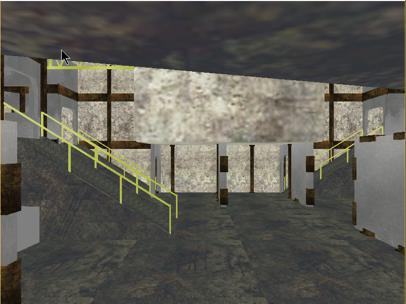
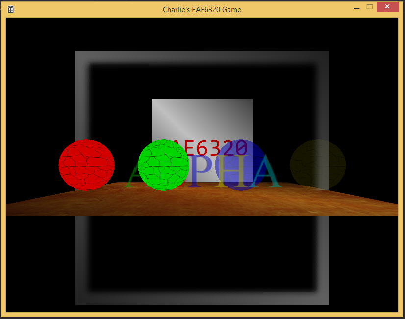
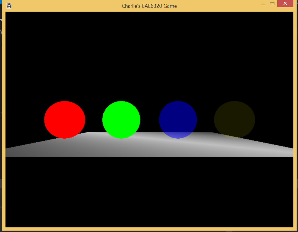
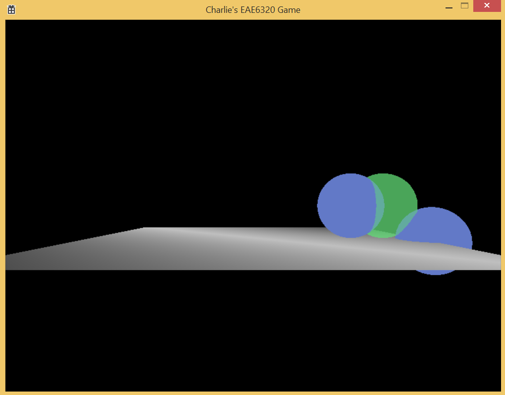
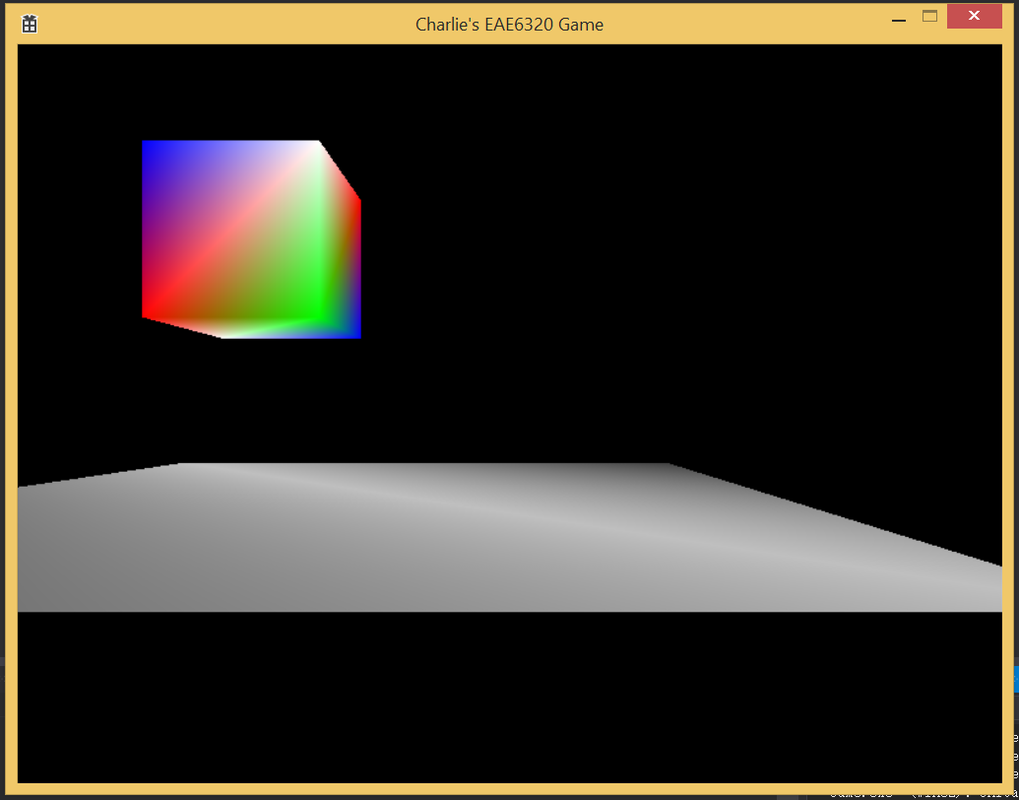
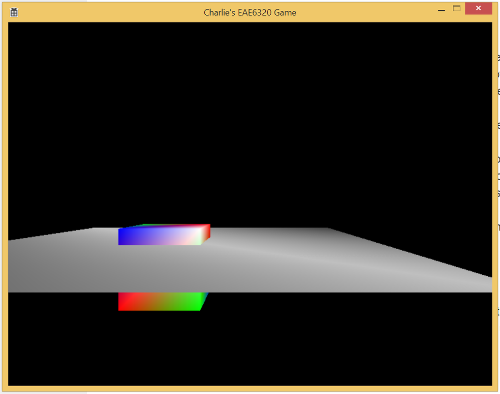
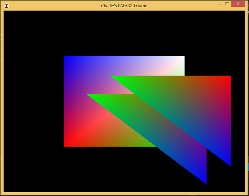
For the new semester, i continue to hone my engine. The first assignment is to load a scene made in Maya as the background of the game. The following is the pic after accomplishing:
Picture
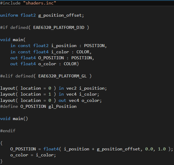
The second assignment is to create drawing debug primitive mechanism for the engine. As I have both D3D and OpenGL rendering in different platform settings, I choose to add it to OpenGL code first.

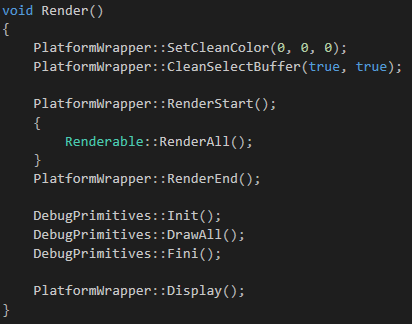
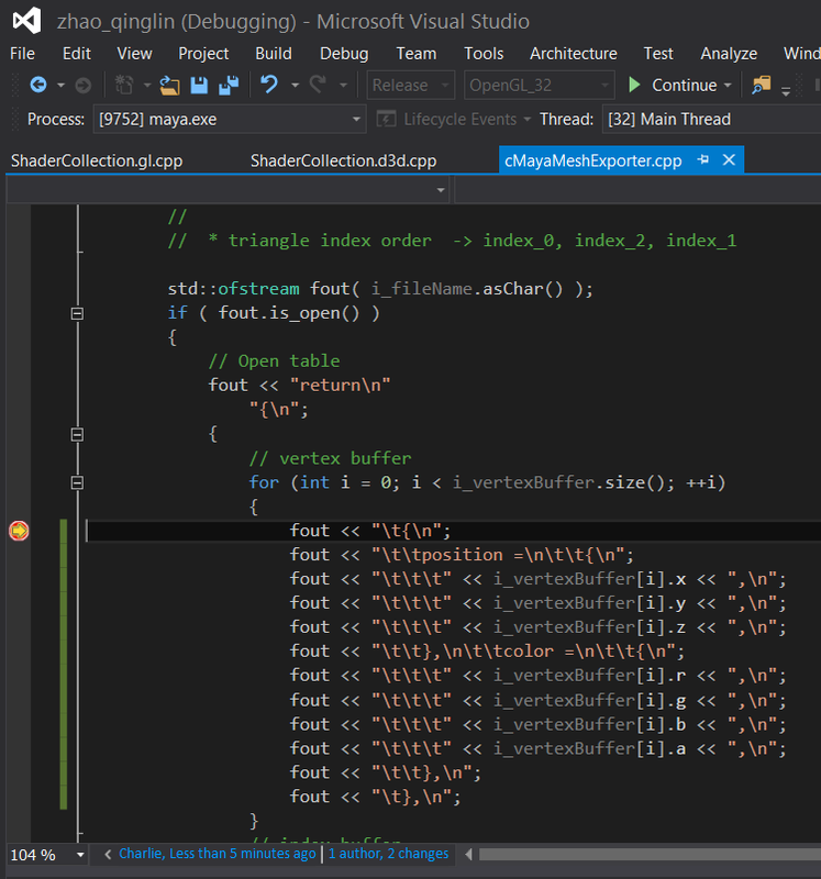
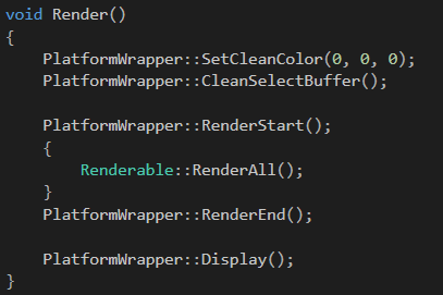
Considering debug primitives will be disabled in release build, I decide to use render list to draw primitives. Then consider the functionality requirement that this is supposed to be used easily, I decide to use a header declaration with drawXXX() methods, which will add primitive object to a render list which will be deleted once after that object being rendered. So then i need initialize, render and cleanup methods besides drawXXX() methods. That's all about interface. Due to different characteristics of various primitives, various primitive classes are derived from Primitive base class, in which a virtual method draw() and color member variable are located. During run time, user of debug primitives just need to include DebugPrimitives header which contains interface. The draw method add Primitive reference to the debug primitive render list which will be called after vertex array objects (VAO) are rendered. The following is the structure for of main render function:
Picture
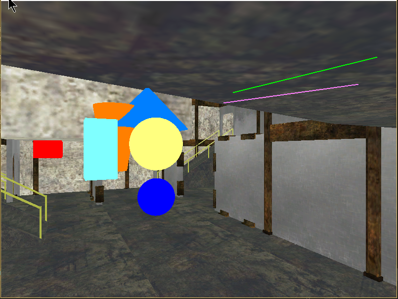
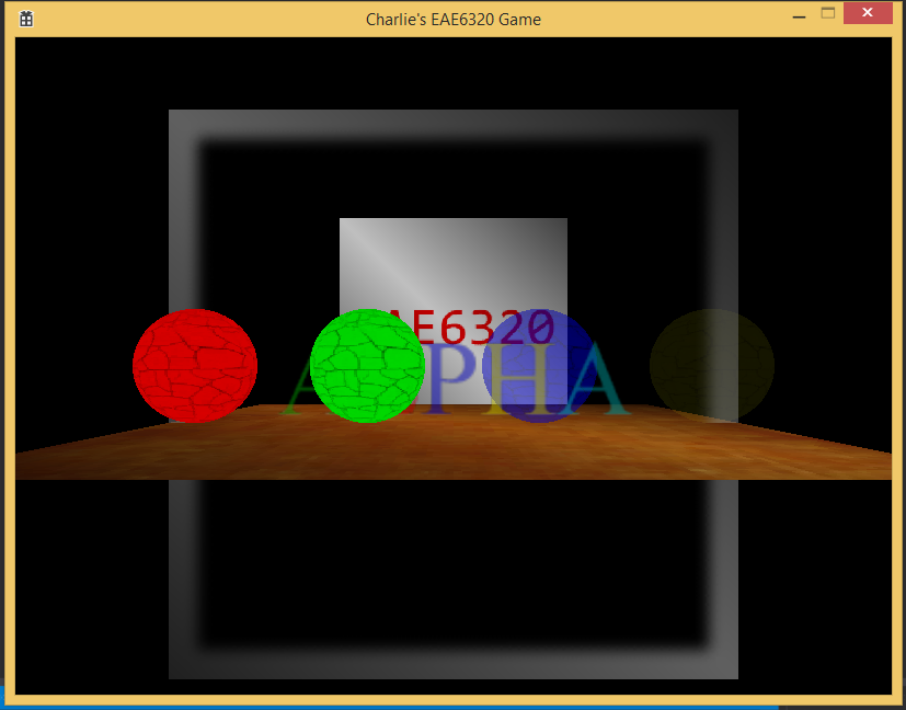
The following is an effect figure after line, cube, sphere and cylinder primitives added to the screen:
Picture
Here's the executable files which includes a release build where debug primitives could not be observed and also a debug build in which button [p] can turn current primitives on/off. Besides, you could traverse the scene using button [a] & [d] for rotation around vertical direction, [w] & [s] for translation along vertical direction, [j] & [l] for parallel movement, [i] & [k] for moving forward and backward.
assignment02.zip
File Size: 5483 kb
File Type: zip
Download File

0 Comments

EAE6320 Final Project

12/18/2015

0 Comments

 
About my final project, I did a 2d top-down shooter paying respect to my childhood favorite nes game Life Force. Here's a pic for life force 4th level:
Picture
As one of the best shooters on NES platform, the most interesting part of it is that you could upgrade your fighter by collecting energy creates in the level. Energy level 1 boost your moving speed. Energy level 2 gives your missile ability and second upgrade on this makes missile faster (which is different in my implementation that second upgrade allows 2 sets of missiles in the screen). Energy level 3 upgrade gives you wave bullet which guarantees wider bullet width and it grows as far as the bullet moves, shown as following:
Picture
In my implementation, I haven't implemented scaling vertex in mesh and collider according to distance from the fighter so my wave bullet doesn't change size. Energy level 4 upgrade gives you laser bullet which shows in picture 1. It's a "one shot until recycle" bullet which behaves different then default or wave bullets, after one shot, the fighter or "option" (I'll explain later) will shoot out a serial of bullet which could do multiple damage count until depleted. But the second shot can only be made if all previous shots are out of screen or collided with enemy. This character makes laser a powerful but less flexible weapon. The energy level 5 upgrade is the most amazing invention in the game it's called "option". It's the little shining thing next the the fighter, it has no collision with other object and do the same attack as the main fighter. My way to implement it is adding another child Fighter GameObject to the main Fighter GameObject. Option would enter Fire() logic when main ship controller receives fire input. Also the pattern for option to move is actually always n steps from its parent object. So the controller of the option would move only when parent object set current move from parent movement trace list. There's another interesting mechanics for "option" that if the main fighter is destroyed, options would be come individual object flying to the coming direction, if the new generated fighter could intercept them half way, they get attached again. You can have at most two options. The 6 level upgrade is called force which means a protector over the ship and ship could immune to destroiable enemy/bullet for 3 times. I'm very happy that I implemented most of the fighter game mechanics of the original game except missile crunches wall and wave bullet increase size.

About enemy part, i create them as inert GameObjects and they get enabled and come to screen only when time comes. Before that, physical system (collision and update), rendering system (mesh, texture and sprite animation), controller system would not update with these inert objects. World system is keeping track of wakening up these inert objects. Different enemy have different hit points. Player can also gain energy creates by destroy special enemies. 

Memory is carefully managed in my game, take an enemy object as example, they only get awaken when at the right timing and then considered by functioning systems, they get destroyed if bullets killed them or they fly out of the screen area. During destroy object, it's shared_ptr reference is released in every components (renderable, collidable, controller) and also world GameObject list. Then in its dtor, component dtor are called and finally the object itself. Another principle I'm keeping is to minimize calling ctor and dtor during the game, especially ctor. 2 options and the main fighter has bullet and missile pools, after flying out of the screen or collided with matched types in collision mask, it get "hidden" to non-observable locations and reused after next fire. This would keep the game as fluent as it should. Thinking of the original game in 1986, hardware is limited. I see that they would like to keep resources in real time update pool as small as possible and try to do the same.

A game is not a good one without sound effects. I also added sound library based on XAudio2 which works depending on callbacks. It's very nice to see these old sprites work with familiar sounds.

Thanks for JP and Joe's class, I have a pretty reliable game engine to create my beloved game. It's very efficient to work with the engine because I know it's mechanics very well. I also added component based design in its structure that it's a little bit like no-graphic-interface unity. I really like the feeling of gathering assets and make them work perfect with the game. I would like to add scaling next so I could reuse meshes in the game.

During making the game, I started to feel why certain design decisions are made so the game turns out to have its shape. When I was playing the game before on TV during 90s. I sometimes see the force effect not rendered for a while and sometimes the fighter itself doesn't get rendered but the force effect comes back. That's all because limitation of NES console only allowing 8 sprites on the same rendering horizontal line. Although less limited by current PC, I still want to respect the old game makers and their wise decisions.

I like the course a lot because I realized that I should delve into structure design more than ever before, especially considering my current job. I'm getting a better sense of component based system, but this is mostly used in game industry. For my work in medical ultrasound system, I need to study more about pipe, filter and parallel programming design techniques. I'm sure I have my passion in game programming all the time. If currently it's not used in a job, it would come out later in another form. If we could secure what we're going to work on in the midterm, probably people with more passion could have more preparation for their project. That's just a little suggestion i have for our course.

About general good code, during the last 4 months in my job, I was working on QA from time to time. Company purchased Coverity service and I was using that to improve code quality. What comes to my mind first is always memory leak. More RAII is mostly a good approach to improve code quality and maintainability. Conditional/partial initialization is another problem that often happens that I would make sure always initialize everything and free everything in ctor dtor. Also paying attention to McCabe complexity is good for code structure. Singletons are evil creatures and should be mostly avoided. Static analysis tool has its limitation. Run time efficiency would also be important. Cache friendly code and better code structure could help. Unit tests and TDD are important to improve code reliability and reduce future trouble.
0 Comments

EAE6320 Assignment13

11/27/2015

0 Comments

 
Picture
above is the material binary file with solid eae6320 texture. After array of uniform data, comes array of texture data, which contains pairs of texture path (in red) and sampler uniform name (in blue). These will be extracted to make temp string vectors in load time.

I choose to create another texture2d class just to be more structured. At graphics initialization, a pointer to d3d device is copied in initialize() method where gl implementation leaves it blank. At load time, texture data and sampler handle will be set in material ctor. At run time, texture is applied in setting material uniform function in material class by calling Texture2D::SetMaterial(size_t unit) where unit is unused by d3d implementation. Material class stores vector of textures of current material.

The following two figures are separately my d3d and gl screenshot:
Picture
Picture
As JP informed, gl implementation looks more "blurry" than d3d version. I'll add scaling in my next assignment also.

Here's my executable
assignment13.zip
File Size: 2594 kb
File Type: zip
Download File

0 Comments

EAE6320 Assignment12

11/25/2015

0 Comments

 
The straight benefit for using materials is that a lot of objects share the same effect while having different appearance. Take iron table and wood table as example, they share the same rendering setting such as same shader, depth test settings, while they use different color or texture during rendering to show themselves as iron or wood. So we can still keep the old way that effect may not need to be changed while rendering several objects.

Here's a screenshot of my human-readable material file:
Picture
Effect path is extracted for reading effect binary at run time. Then there's a Uniform block which contains arrays of uniforms. In each block, uniform name is used to set handle at run time. Then there comes the value block which contains 1 to 4 floats to meet different vector size need in shader. Then shader type is specified for Direct3D to specify which shader should we get const table and then get handle from. 

The following is a screenshot for my direct3d transparent blue material:
Picture
As mentioned above, effect path comes first. Then comes the count of uniforms, which is optional. Then comes array of uniforms. The red line part is the uniform handle, which is a 64 bit nullptr as default. Then the blue part shows the shader type, in my case vertex is 0 while fragment is 1. The number of values we need for a uniform is flexible but i choose to hold it in a fixed size container (4 floats). The count is needed to know how many values is actually useful in run time. The green part contains 4 float values. Then comes the count of values shown in black part. There's no particular reason for choosing this sequence. Then after the array of uniforms, there comes the name array for uniforms shown in brown. This is used to set handle at load time.

Different platform has different binary material because type for handle is different and they have different default values. It's the same between configurations in my case though.

Here's a screenshot of my scene:
Picture
Same mesh is used for all four spheres. The mesh vertex color is white. The red sphere has is solid material with rgb (1, 0, 0) so only red passes the filtering. Green is similar just with rgb (0, 1, 0). These two materials use default.effect which disables alpha blending. As for blue and yellow shperes, they have separate rgb of (0, 0, 1) and (1, 1, 0). Blue material has an opacity of 0.5 while yellow has it as 0.1. In their shared effect, alpha blending is enabled and also exists fragment shader uniform for setting alpha independently.

Here's my executable:
assignment12.zip
File Size: 57 kb
File Type: zip
Download File

0 Comments

EAE6320 Assignment11

11/17/2015

1 Comment

 
The exporter project doesn't have any dependency relation with any other projects in the solution. The output from the exporter is used by manual process to export lua mesh file. The builder projects then use the mesh file to generate the binary. So no projects should be dependent on exporter project. Exporter project doesn't depend on any projects to build the mll.

Here's a screenshot of plug-in manager:
Picture
Here's a screenshot of exporter debug:
Picture
Here's a screenshot of my scene:
Picture
Here's a screenshot of human-readable effect file:
Picture
There's no particular reason for choosing this format. The structure is rather plane because contents are pretty much unique entries. For the optional render state, default value will be set if absent from lua file as JP suggests.
Also using an uint32_t as optional bits container. I'm currently using bit 0 for alpha transparency, bit 1 for depth testing, bit 2 for depth writing and bit 3 for face culling. To set a bit, use container |= 1 << BIT_INDEX. To get a bit, use container & 1 << BIT_INDEX.
​
Here's screenshot for default effect and transparent effect binary:
Picture
Picture
The structure of binary effect is first file name for vertex shader followed by \0, then name for fragment shader followed by \0, then a 4 byte unsigned int followed by \0 (which is not necessary). For default effect, the unsigned int value is 0x0000000E indicates 1110 on lowest 4 bits. This means we're disabling alpha transparency, enabling depth testing, writing to depth buffer and also face culling. For transparent effect, the value is 0x00000003 which means 0011 on lowest 4 bits, indicating we're enabling alpha transparency and depth testing while disabling writing depth buffer and face culling. The optional bits are added to the last part of the binary file just by intuition. When reading binary file, this value is get by calculating the offset by strlen(vertex) + strlen(fragment) + 2, then cast the pointer into a pointer to uint32_t.

For alpha blending, we're currently using srcColor * srcAlpha + backColor * (1 - srcAlpha), which is intuitive. A blue glass with transparency of 0.5 will appear 0.5 of its own color and another 0.5 of what's behind the glass in observers' eyes. The reason to render from back to front is because transparent objects doesn't write to depth buffer, so if there're solid objects rendered behind transparent objects both in render sequence and z value may write to z buffer and cover the transparent objects, making that visually unrealistic. We need to render objects that doesn't write to depth buffer last so that we can get blended color from the basic calculation above. Face culling should also be disabled for transparent objects because when object is transparent we can clearly see its back side.

Here's my executable:
assignment11.zip
File Size: 59 kb
File Type: zip
Download File

1 Comment

EAE6320 Assignment10

11/8/2015

2 Comments

 
Picture
We have three transformation matrix in vertex shader. The first one transform 3d vertex from local coordinate to world coordinate. Speaking of box, we consider the local coordinate center as the center of the box. A vertex at (1, 1, 1) in its local coordinate will be first transformed to work space using local_to_world transformation matrix. World space is self-explained that that's where every object stays in. Things with same local position could have different position in world, and vice versa. Then we need to perceive the world from camera, this means we need to apply a world_to_view transform to the previous result. The default position and direction of camera is at (0, 0, 1) and looks at (0, 0, -1) direction. We apply that second transformation to get where things are from the whole view plain. Still, we need another transformation matrix to apply camera specific parameter where open angle and truncation planes come into place. After applying these three matrix, we get the picture above.
Picture
Here's a picture where two objects intersect. Our depth buffer is 16 bits which means 65536 differences. From our far plain to near plain we have 100 - 0.1 = 99.9 unit length. 99.9 / 65536 = 0.0015 is the minimum difference we can tell in depth buffer. In each frame, the depth is cleaned to be the value representing the furthest distance. OpenGl use a float between 0 to 1 here. 1 means the furthest. Then we start to draw the first object. When drawing a pixel for the first object, the first object that could be seen is definitely nearer to the screen than the furthest truncation plain. So we draw its color in color buffer, also update its depth in depth buffer. When we're drawing the second object, depth test still needs to be done with current pixel depth value. If it's not nearer to the observer, we can tell it's hidden by previous drawing pixel so we don't need to draw that. We use less or equal to as depth function because for effects like bump map, we'll process the same point for several times, the default less function will truncate later process after the first write. 
Picture
Picture
These above are my .lua and .binary version of floor mesh. I just added the z value after x and y. The change could be observed in binary file that after two counts, every vertex has 3 x 4 byte position and 4 x 1 byte color, followed by 2 x 3 index at last.

For the camera, it's a derived class from component class. It keeps a list of cameras for future cull rendering purpose. It's in parallel hierarchy as Renderable class. To create a camera object. First create a gameobject with position, then add camera component to it, then as assignment requirement, add controller component to it. The first camera created is automatically set as main camera which could be accessed as public unless set otherwise. Culling layers will be added for Renderable and Camera later for a more versatile functionality.

Here's the executable:
Current control is asdw for box xy, rf for box z, jkli for camera xz movement.
assignment10.zip
File Size: 45 kb
File Type: zip
Download File

2 Comments

EAE6320 Assignment09

11/2/2015

1 Comment

 
Picture
Here's my platform-independent render method. PlatformWrapper is a namespace containing helper functions. For cleaning buffer, a uint8_t rgb color is first set, with 0, 0, 0 being default argument. There's a range conversion for gl onlu. Then CleanSelectBuffer method is called with three possible boolean arguments indicating if to clean each buffer by setting their separate bit in each platform. Here default argument is to clean color buffer while leaving the other two untouched for now. RenderStart() & RenderEnd() are for D3D use as JP mentioned. Renderable info is kept in a multimap. RenderAll() iterates through the map and call seteffect, setuniform and drawmesh for them. Display just swap the buffer to show the rendered content with separate implementation.
Picture
I chose d3d types by random. The differences between implementation is basically on variable declaration and function argument list. Redefine platform separate types and also platform specific required naming into common convention is necessary to keep public area platform independent. For instance, output positions are both defined to O_POSITION to make main function platform independent.
Picture
For dependency files, I just add another table called Dependency just as optional arguments. These files are checked to get the latest modified time to compare with build target.

Here's an executable of mine:
assignment09.zip
File Size: 42 kb
File Type: zip
Download File

1 Comment

EAE6320 Assignment08

10/29/2015

0 Comments

 
Picture
This is my human-readable effect file. Simple enough, it indicates path for vertex shader and fragment shader in a key-value pair pattern. There's no special reason for such a design but simple enough as well as fulfill user requirements for now. This may face redesign in future.
Picture
This is my binary effect file. As we can observe, it simply contains two strings which represent name for binary vertex/index shader separately. And after each string, an '\0' is added to indicate string end. This is used when reading strings from buffer. At run time, the first string is get by std::string(buffer). std::string ctor will automatically truncate string at first '\0' it meets. Then the beginning index of the second string is got by offset = strlen(FIRST_STRING) + 1. Do another std::string(buffer + offset) will get the second string.

I choose to use one builder for both shaders as JP did. Optional arguments will be practical for many builders so it's a capable candidate to add to AssetToBuild file. I would consider slightly increasing in build time acceptable compared to duplicate code. For assets need optional arguments to build, structure looks like this:

{
    Tool = "ShaderBuilder.exe",
    Assets =
    {
        "lininterpvertex.shader",
    },
    Optional =
    {
        "vertex",
    }
}

Other assets look like this:

{
    Tool = "EffectBuilder.exe",
    Assets =
    {
        "default.effect",
    }
}

The reason for having custom defined macro for shader is to make it more flexible. We can have different sets of defined settings such as having a logo version and a no-logo version but both with debugging enabled.
Picture
Picture
Above 2 figures are debug vs release version of d3d vertex shader. Release version is much shorter than debug version. This is because we pass in an allowing optimizing argument for release version. It's the shortest possible but containing all info.
Picture
Picture
Above 2 figures are debug vs release version of gl vertex shader. Release version is slightly shorter only because it gets rid of newline character in the file. It's reasonable to do so in a release build because we need less readability on release version, while we need to see a better line-divided organizing file while debugging.

Here's a copy of my executable
assignment08.zip
File Size: 42 kb
File Type: zip
Download File

0 Comments

EAE6320 Assignment07

10/10/2015

0 Comments

 
Picture
So this week we worked on getting things moving around. In my case, you could use "aswd" (lower case) to move both triangles around.
The first intuitive thing that could help could be thinking over to decide which engine structure to apply for future. I finally took the component approach which kind of intentionally mimic Unity. I have GameObject which contains position and name info. It also keeps a list of possible components. Every component keeps a reference of the GameObject to which it is added. Renerable inherits from component class and keeps a static list of renderable components. It calls every renderable component to set effect (if necessary), set uniform position obtained from GameObject reference, and then draw mesh. Controller is another child class of component. WSAD controller used for triangles inherits from controller class which keeps a list of all controller component waiting to be called in update just like renderable components. As two separate controller is added to each triangle, time class is refactored into class whose instance is kept with controller instance to measure time separately.

During refactoring, forward declaration is preferred in order to save compile time as well as avoid circular dependency. Meanwhile, I was unfortunately that I met the weird bug that d3d9xshader is could not be found during building. Forward declaration also works for solving this problem.
Compared to vertex data, uniforms are variables that could be modified during frame to affect graphic effects. Vertex data is more "fixed" data that used to express all-time constant such as relative position of vertex from the center of gameobjects. The benefit of using uniform for representing offset is that we could change relatively fewer parameters compared to changing all vertex data. In future assignments, uniforms will also be added to fragment shader to manipulate color effects. 

Here's a copy of executable:
assignment07.zip
File Size: 46 kb
File Type: zip
Download File

0 Comments

EAE6320 Assignment06

10/1/2015

0 Comments

 
So this week, we started push a little bit further on both mesh processing and shader creating.
Picture
Above is a figure showing my whole binary file for a square and a triangle.

As you may see, the sequence of 4 pieces of data in my case is NumOfVertex, NumOfIndice, VertexData and IndiceData. The reason to put counts ahead is simply that their size is fixed. In the case of processing multiple lua meshes, we need to rewrite part of the file. If 2 counts comes first, then we just need to move IndiceData from its beginning because we will write in new VertexData, while previous VertexData doesn't need to be moved.

The reason number must come first is that they should be used to calculate the size of the data chunk. No one would know how much we should read unless we know how many corresponding data there are.

Binary data is fast in process because it's pure std library work with the minimum data size. It saves time when loading a scene in the game. It's also smaller in size. The more human readable an asset is, it's more likely to be large sized compared to its binary peer. When we ship a product build, we also want to save disk space for users. Human-readable assets has its advantage just as the name suggests. As asset author or engineers, we need to look into assets efficiently to modify assets. So that's necessary to have both binary and human-readable version of the same assets for our case.

My triangle lua mesh is 4096 bytes while binary mesh is just 56 bytes.

Here's my code loading binary mesh data into memory:
Picture
I also modified my AddTriangleMesh to static class that no longer holds instance of separate triangle mesh pieces.

Here's a picture showing how I load my shader file.
Picture
The class shader collection also contains a map keeping key-value pairs which represent effect name and effect instance. User of the class could create multiple effects with different name and set them during rendering call with their own name.

Here's how I call set effect in rendering code:
Picture
Simple and short enough. If a name is not given at creation, an effect instance will have a default name, this name will also be used as the default input of set effect method.

Here's a copy of my executable:
assignment06.zip
File Size: 36 kb
File Type: zip
Download File

UPDATE:

So I made an inappropriate decision merging multiple binary file into one. Doing so means it's hard to have different effects for different meshes. I modified my TriangleMesh class back to preserving a static multimap keeping all mesh instances labeled with a name ("default" by default). DrawAllMeshes method is used to draw all meshes. DrawMeshesWithName method is used to draw all meshes with the same name.

Here's the new executable:
assignment06.zip
File Size: 37 kb
File Type: zip
Download File

0 Comments
<<Previous

    Archives

    January 2016
    December 2015
    November 2015
    October 2015
    September 2015
    August 2015
    January 2015

    Categories

    All
    Campus Game Programming
    Free Bla

    RSS Feed

Powered by Create your own unique website with customizable templates.